CHECKERED FLAG!!
Practice, practice and practice to get the best result.
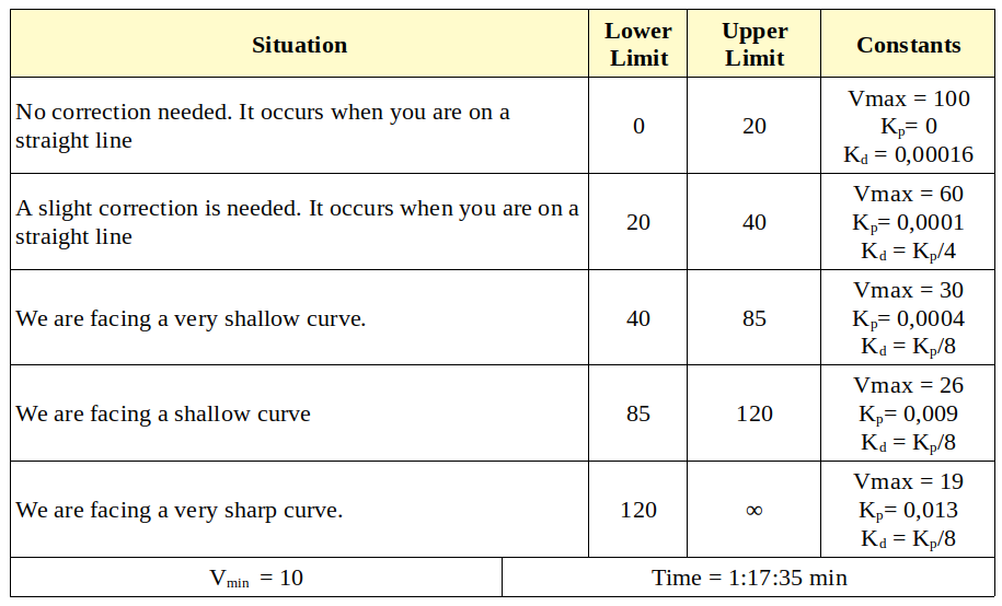
After achieving a complete lap of the circuit without damage, we want to adjust the parameters as much as possible in order to achieve an optimal result. An optimal result must meet the stability requirements and remain on the red line at all times. This maximum adjustment is achieved through a PD controller, testing which combination of proportionality constants and speeds is the one that gives us the best results.
The values that these parameters take in a first approximation are shown below.

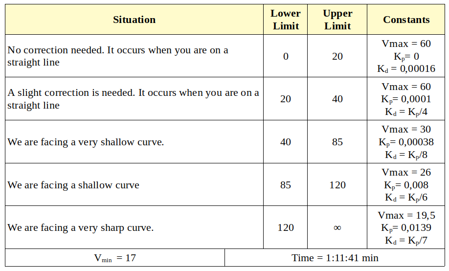
In the next step, we try to decrease the oscillation of the F1 in the curves, so that the driving is smoother and the time decreases. In the next step, we try to decrease the oscillation of the F1 in the curves, so that the driving is smoother and the time decreases. We experience through simulation the different combinations that can lead us to achieve our goal. And so, it is how we have managed to make our best lap in an approximate time of 1:11:41 min and meeting all the established requirements.
And here you have our fast lap!
In the following video you can see the simulation of our best turn to the right, while on the right you can see the image captured by the RGB camera of F1 and the result of the processing of that image. Black point that appears in the mask on the left is the point that is used to calculate the error made in each iteration.
This good result is achieved by configuring the PD controller with the following parameters.

See you soon!
I hope it has been useful and entertaining because this has only just begun. We finish this practice and we will continue to upload more entries with new challenges of development of Computer Vision in the world of robotics. See you soon!
